What is Inverse Kinematics?
When multiple objects are linked together with parent-child-relations the structure is called object hierarchy. In an object hierarchy parents usually transform their children as they are transformed themselves. These transformations are usually defined by rotation angles around pivot points, translations along pivot axis and axial scaling factors. Each object applies its parent’s transformation to its own. This way all of the objects in the hierarchy get transformed. This method of applying transformation is called forward kinematics.
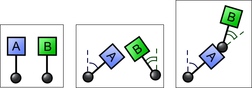
Sometimes it’s necessary to set transformation for an object in the hierarchy by hand. Often this brakes the hierarchy because this object doesn’t obey its parent’s transformation anymore. To avoid breaking of the hierarchy some other objects have to adapt their transformations. This adaption is called inverse kinematics and it can be made to happen automatically.
How to use IK?
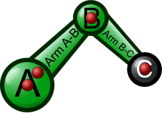
Bongo 2’s IK feature could also be called automatic keyframing. An IK structure is a basically a chain (parent child relation) of objects having a start (driver) and stop (goal) point. It calculates the behaviour or transformation (movement, rotation, scaling) of the objects in the chain.
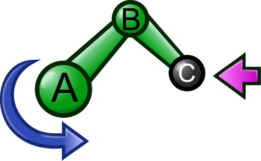
Here is a simple example.
The red dots are showing where the pivots are in this model.
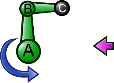
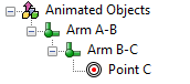
The hierarchy looks like this:
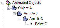
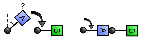
We want the Object A to rotate, Point C to stay in place and the rest of the chain to follow along.
By adding rotation animation data to Object A, the whole chain starts to move around.
In Bongo 1.0 you would have to correct this movement manually, by adding lots of keyframes.
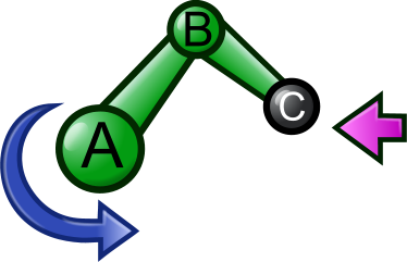
Doing it manually would also mean that the result would not be exact. The end Point C would most likely move around no matter how carefully you would set it up.
The easiest solution is to make Bongo 2 do the calculation on your behalf, by using the IK-feature.
The IK-Settings for objects can be found on the Object Properties page, under Bongo.
Make the Arm A-B and Arm B-C into joints, in this case you would pick Hinge.
Turning objects into joints means that you give Bongo the permission to move the objects in order to solve the calculation. By specifying which kind of joint you want to use, you tell Bongo in which direction it is allowed to move, rotate, or scale the object. See joint types for more info about how the different joints work.
The Point C will be constrained to its position. This tells Bongo that the goal for this model is to keep this point in the same position. Now by pressing play the piston should start to move and the end point should stay in place.
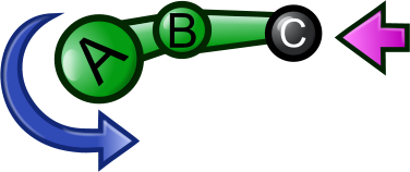
The final IK-view for this example would look like this:

IK View and Joint types
 If you click on the IK view icon in the Animation Manager you can choose to enable the IK view. In the IK view you can see of which components and joint types the IK chain consists.
The icons are the following:
 Hinge – Makes it possible for Bongo to rotate the joint in the x-,y- or z-direction.
 Universal – Makes it possible for Bongo to rotate, scale and move the joint in all directions.
 Telescopic – Makes it possible for Bongo to extend the joint in the x-,y- or z-direction.
 Rubberband – Makes it possible for Bongo to scale the joint in the x-, y- or z-direction
 Goal – The constraint at the end, the endpoint. It tells Bongo that it can stop compute here.
IK error tolerance
IK error tolerance settings in Bongo document properties adjust how accurately IK constraints are held up. Higher number means less accuracy and more wobble. Smaller number means more accuracy and less wobble.
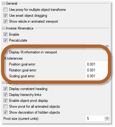
Translation, rotation and scaling have their own tolerance, translation and rotation tolerance are absolute and scaling tolerance is relative. Tolerances are used per axis – each component can have that much error. Setting the translation error to 0.1 means that the constraint object is allowed to be 0.1 units away from the goal along any axis. So it should stay inside a cube centered at the goal and whose sides are 0.2 units.
PreCalculation
 When precalcualtion is disabled, IK is solved from the slider’s current position. For example, you will get two results at tick 50 when you move the slider from tick 10 to 50 and from tick 20 to 50. When precalcualtion is enabled, IK is solved when IK setup is done and the information is stored in the cache. You will always get the same result at tick 50. The slider’s current position won’t make any difference to the result because IK is just replayed once and once again.
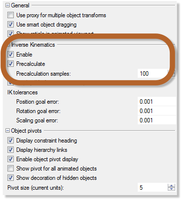
When the precalculation sample is set to, for example, 20 and the timeline length is 100 ticks, then there is one precalculation tick every 5 ticks. Increasing the sample number shortens the distance between precalculation ticks that increases the accuracy of IK, but it will need more time for precalculation. If you have a complicated IK chain or fast moving goals, you will need higher precalculation samples for a better result.
The Precalculation settings can be found in the Bongo Document Options.
IK Tutorials
Basic IK in Bongo
The Whys of IK
PDF Document - The basic why’s of IK
Models Explications.zip
Simple constraint vs IK
Model RoboSnake.3dm
Animate a scissor arm
Model ScissorArmFinal.3dm
Animate a ball arm
Model RobotBallArmStart
Model RobotBallArmFinished
